Brand Name: llamps
Model Number: ILA-10
Place of Origin: China
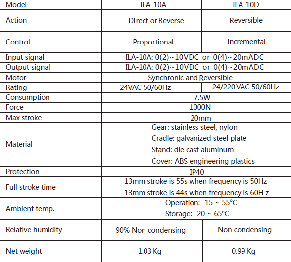
ILA-10A, accepting 0(2)~10VDC or 0(4)~20mA control signal and
providing proportional control.
ILA-10D, providing incremental control, assembled with reversible
motor.
Specifications

Mounting
-Mounting position is upright to horizontal. It is recommended that the
valve be mounted in the upright position in accessible location.
-Sufficient clearance must be allowed for actuator maintenance or
detaching.

S1 Dial Switch Setting
• Position 1 :”OFF” is for voltage output signal,”ON” is for current output signal;
•Position 2 :”OFF” is for voltage input signal,”ON” is for current input signal;
S2 Dial Switch Setting
•Position 1:OFF:equivalent-linearity flux characteristic,
ON:Equivalent-percentage characteristic;
•Position 2:OFF:Input/Output single start point is 0 (0-20mA or 0-10V)
ON:Input/Output single start point is 20%(4-20mA or 2-10V)
•Position 3:OFF:RA Model(Control signal increase, actuator central shaft
going up)
ON:DA Model(Control signal increase, actuator central shaft going
down)
•Position 4:OFF:When voltage input signal is cut, the actuator central shaft will
running to the top;
When the current input signal is cut, the actuator central shaft will running
to the bottom;
ON:When voltage input signal is cut, the actuator central shaft will running
to the bottom;
When current input signal is cut, the actuator central shaft will running to
the bottom;
4. Actuator for Adjusting
According Mounting Diagram for actuator/valve,firstly follow the requirements to
finish setting the dial switch,then connect the power input/output signal wire,push
“self-adaptation” button over 3 seconds,you can check the shaft operating up to the
top,then operating down to the bottom,the indicator flashing at same time. About
after 200 seconds the indicator stop flashing,,in the time, the electronics control valve
and the valve body self adaptation process finish,valve connect to the actuator signal
cooperation work finish.
Notice:The whole processing only need to be connected 24VAC power supply,It is no
matter with the input/output signal.
Warning:Every time for inputting or outputting signal range need to be repeat the self
adaptation process.


